8086 lab


A Microprocessor is a
programmable, digital logic device fabricated on a single
VLSI chip which can perform a
set of arithmetic and logic operations as per the
.instructions. given by the
user.
Any microprocessor has
minimum three basic functional blocks: Arithmetic Logic
Unit (ALU), Timing &
Control unit, Register array
The user writes his/her
programs using English-like words (called .mnemonics.) and
is known as .assembly language
program. (ALP).
A software called
.Assembler. converts the user ALP into HEX/binary form (called
machine language) which is fed
to the processor. The processor internally decodes
this binary code and performs
the operation.
8086 Internal Block diagram
8086 is a 16-bit processor
having 16-bit data bus and 20-bit address bus. The block diagram of
8086
is as shown. This can be
subdivided into two parts; the Bus Interface Unit (BIU) and Execution
Unit
(EU).
BUS INTERFACE UNIT:
The BIU consists of segment
registers, an adder to generate 20 bit address and instruction
prefetch queue. It is
responsible for all the external bus operations like opcode fetch,
mem read,
mem write, I/O read/write
etc,. Once this address is sent OUT of BIU, the instruction and data
bytes
are fetched from memory and
they fill a 6-byte First In First Out (FIFO) queue.
EXECUTION UNIT:
The execution unit consists
of: General purpose (scratch pad) registers AX, BX, CX and DX;
Pointer registers SP (Stack
Pointer) and BP (Base Pointer); index registers source index (SI) &
destination index (DI)
registers; the Flag register, the ALU to perform operations and a
control unit
with associated internal bus.
The 16-bit scratch pad registers can be split into two 8-bit
registers.
AX AL, AH ; BX BL, BH;
CX CL, CH; DX DL, DH.
Note: All
registers are of size 16-bits.
Different registers and their
operations are listed below:
Register Uses/Operations
AX As accumulator in Word
multiply & Word divide operations, Word I/O
operations
AL As accumulator in Byte
Multiply, Byte Divide, Byte I/O, translate,
Decimal Arithmetic
AH Byte Multiply, Byte Divide
BX As Base register to hold
the address of memory
CX String Operations, as
counter in Loops
CL As counter in Variable
Shift and Rotate operations
DX Word Multiply, word Divide,
Indirect I/O
Assembly Language
Development Tools:
1. EDITOR:
It.s a system software
(program) which allows users to create a file containing assembly
instructions and statements.
Ex: Wordstar, DOS Editor, Norton Editor
Using the editor, you can
also edit/delete/modify already existing files.
While saving, you must
give the file extension as ..asm..
Follow the AL syntax while
typing the programs
Editor stores the ASCII
codes for the letters and numbers keyed in.
Any statement beginning
with semicolon is treated as comment.
When you typed all your
program, you have to save the file on the disk. This file is called
.source. file, having a ..asm.
extension. The next step is to convert this source file into a
machine
executable ..obj. file.
2. ASSEMBLER:
An .assembler. is a system
software (program) used to translate the assembly language
mnemonics for instructions to
the corresponding binary codes.
An assembler makes two
.passes. thro. your source code. On the first pass, it determines the
displacement of named data
items, the offset of labels etc., and puts this information in a
symbol table. On the second
pass, the assembler produces the binary code for each instruction
and inserts the offsets, etc.,
that is calculated during the first pass. The assembler checks for
the
correct syntax in the assembly
instructions and provides appropriate warning and error
messages. You have to open
your file again using the editor to correct the errors and reassemble
it using assembler. Unless all
the errors are corrected, the program cannot be executed in the
next step.
The assembler generates
two files from the source file; the first file, called the object
file having
an extension ..obj. which
contains the binary codes for instructions and information about the
addresses of the instructions.
The second file is called .list file. with an extension ...lst.. This
file contains the assembly
language statements, the binary codes for each instruction, and the
offset for each inst. It also
indicates any syntax errors or typing errors in the source program.
Note: The
assembler generates only offsets (i.e., effective addresses); not
absolute physical
addresses.
3. LINKER:
It.s a program used to
join several object files into one large object file. For large
programs,
usually several modules are
written and each module is tested and debugged. When all the
modules work, their object
modules can be linked together to form a complete functioning
program.
The LINK program must be
run on ..obj. file.
The linker produces a link
file which contains the binary codes for all the combined modules.
The linker also produces a
link map file which contains the address information about the linked
files.
The linker assigns only
relative addresses starting from zero, so that this can be put
anywhere in
physical primary memory later
(by another program called .locator. or .loader.). Therefore, this
file is called relocatable.
The linker produces link files with ..exe. extension.
Object modules of useful
programs (like square root, factorial etc) can be kept in a
.library.,
and linked to other programs
when needed.
4. LOADER:
It.s a program used to
assign absolute physical addresses to the segments in the ..exe.
file, in
the memory. IBM PC DOS
environment comes with EXE2BIN loader program. The ..exe.
file is converted into ..bin.
file. The physical addresses are assigned at run time by the loader.
So, assembler does not know
about the segment starting
addresses at the time program being assembled.
5. DEBUGGER:
If your program requires
no external hardware, you can use a program called debugger to load
and run the ..exe. file.
A debugger is a program
which allows you to load your object code program into system
memory, execute the program
and troubleshoot or debug it. The debugger also allows you to
look at the contents of
registers and memory locations after you run your program.
The debugger allows you to
change the contents of registers & memory locations and rerun the
program. Also, if facilitates
to set up .breakpoints. in your program, single step feature, and
other easy-to-use features.
If you are using a
prototype SDK 86 board, the debugger is usually called .monitor
program..
We would be using the
development tool MASM 5.0 or higher version from Microsoft Inc.
MASM stands for Microsoft
Macro Assembler. Another assembler TASM (Turbo Assembler) from
Borland Inc., is also
available.
How to Write and Execute
your ALP using MASM?
Steps to be followed:
1. Type
EDIT at the command prompt (C:\>\MASM\). A window will be opened
with all the
options like File, Edit etc.,
In the workspace, type your program according to the assembly
language syntax and save the
file with a ..asm. extension. (say test.asm)
2. Exit
the Editor using File menu or pressing ALT + F + X.
3. At
the prompt, type the command MASM followed by filename.asm (say,
test.asm). Press Enter
key 2 or 3 times. The
assembler checks the syntax of your program and creates ..obj. file,
if there are no errors. Otherwise, it indicates the error with line
numbers. You have to correct the errors by
opening your file with EDIT
command and changing your instructions. Come back to DOS prompt
and again assemble your
program using MASM command. This has to continue until MASM
displays .0 Severe Errors..
There may still be .Warning Errors.. Try to correct them also.
4.
Once you get the ..obj. file from step 3, you have to create the
..exe. file. At the prompt, type
the command LINK followed by
.filename.obj. (say, test.obj) and press Enter key. (Note that youhave to give the extension now
as ..obj. and not as ..asm.). If there are no linker errors, linker
will
create ..exe. file of your
program. Now, your program is ready to run.
5. There
are two ways to run your program.
a) If your program accepts
user inputs thro. keyboard and displays the result on the screen,
then
you can type the name of the
file at the prompt and press Enter key. Appropriate messages will be
displayed.
b) If your program works with
memory data and if you really want to know the contents of
registers, flags, memory
locations assigned, opcodes etc., then type CV test (file name) at
the
prompt. Another window will be
opened with your program, machine codes, register contents etc.,
Now, you also get a prompt >
sign within CV window. Here you can use .d. command to display
memory contents, .E. command
to enter data into memory and .g. command to execute your
program. Also, you can single
step thro. your program using the menu options. In many ways, CV
(Code View) is like Turbo C
environment.
Once you are familiar with the
architecture and basics of assembly language tools, you can start
typing and executing your
program.
Instructions for Laboratory
Exercises:
1. The programs with comments
are listed for your reference. Write the programs in observation
book.
2. Create your own
subdirectory in the computer. Edit (type) the programs with program
number and
place them in your
subdirectory. Have a copy of MASM.EXE, CV.EXE and LINK.EXE files in
your
subdirectory. You can write
comments for your instructions using Semicolon (;) symbol.
3. Execute the programs as per
the steps discussed earlier and note the results in your observation
book.
4. Make changes to the
original program according to the questions given at the END of each
program
and observe the outputs 5. For part A programs,
input-output is through computer keyboard and monitor or through
memory.
6. For part B programs, you
need an external interface board. Connect the board to the computer
using
the FRC available. Some boards
may require external power supply also.
7. Consult the Lab
In-charge/Instructor before executing part B experiments.
8. The assembler is not case
sensitive. However, we have used the following notation: uppercase
letters
to indicate register names,
mnemonics and assembler directives; lowercase letters to indicate
variable
names, labels, segment names,
and models.
Program 1:Design and develop an assembly language program to search a key element “X” in a list of ‘n’ 16-bit numbers. Adopt Binary search algorithm in your program for searching.
Program 1:Design and develop an assembly language program to search a key element “X” in a list of ‘n’ 16-bit numbers. Adopt Binary search algorithm in your program for searching.
.model
small
.stack
10
.data
a dw
05h,10h,15h,20h,25h,30h,35h
n
equ 07
key
dw 10h
msg1
db 'Key found$'
msg2
db 'Key not found$'
.code
mov
ax,@data
mov
ds,ax
mov
ax,key
mov
cx,0
mov
dx,n
add
dx,dx
sub
dx,1
next: cmp
cx,dx
jg
notfound
mov
bx,dx
add
bx,cx
mov
si,bx
shr
bx,1
jnc
count
sub
si,1
count: cmp
ax,a[si]
je
found
jl
lhalf
add
si,2
mov
cx,si
jmp
next
lhalf: sub
si,2
mov
dx,si
jmp
next
found:
mov dx,offset msg1
jmp
exit
notfound:
mov dx,offset msg2
exit:
mov ah,09h
int
21h
mov
ah,4ch
int
21h
int
3
end
Output:
Key Found
Program 2: Design and develop an assembly program to sort a given set of ‘n’ 16-bit numbers in ascending order. Adopt Bubble Sort algorithm to sort given elements.
Program 2: Design and develop an assembly program to sort a given set of ‘n’ 16-bit numbers in ascending order. Adopt Bubble Sort algorithm to sort given elements.
.model
small
.stack
10
.data
a
db 03h,01h,04h,02h
count
dw 04
.code
mov
ax,@data
mov
ds,ax
mov
bx,count
dec
bx
outloop:mov
cx,bx
mov
si,0
inloop: mov
al,a[si]
inc
si
cmp
al,a[si]
jl
down
xchg
al,a[si]
mov
a[si-1],al
down: loop
inloop
dec
bx
jnz
outloop
mov
ah,4ch
int
21h
end
Output:
d
ds:0000 01 02 03 04
3. Develop an assembly language program to reverse a given string and verify whether it is a
palindrome or not. Display the appropriate message.
.model small
.stack 10
.data
m1 db 'palindrome$'
m2 db 'not palindrome$'
str1 db 'aabbaa$'
l1 dw $-str1-1
str2 db 25 dup(?)
.code
mov ax,@data
mov ds,ax
mov es,ax
mov si,0
mov di,l1
mov str2[di],'$'
mov cx,l1
dec di
up: mov al,0
mov al,str1[si]
mov str2[di],al
dec di
inc si
loop up
mov si,offset str1
mov di,offset str2
mov cx,l1
cld
repe cmpsb
jz pal
mov dx,offset m2
jmp exit
pal: mov dx,offset m1
exit: mov ah,09h
int 21h
int 3
end
Output: String is Palindrome
4. Develop an assembly language program to compute nCr using recursive procedure. Assume that
‘n’ and ‘r’ are non-negative integers.
.model small
.stack 10
.data
n dw 4
r dw 2
org 10h
ncr dw ?
res dw ?
.code
mov ax,@data
mov ds,ax
mov ax,r
call fact
mov bx,res
mov ax,n
sub ax,r
call fact
mov ax,res
mul bx
mov bx,ax
mov ax,n
call fact
mov ax,res
div bx
mov ncr,ax
int 3
fact proc
cmp ax,0h
je exit
push ax
dec ax
call fact
pop ax
mul res
mov res,ax
ret
exit:mov res,1h
ret
fact endp
end
Outpt: res= 6
5.
Design and develop an assembly language program to read the current
time and Date from the system and display it in the standard format
on the screen.
TIME
PROGRAM :
.model
small
.stack
10
.data
msg
db 13,10,"the time is:"
time
db ?,?,':',?,?,"$"
.code
mov
ax,@data
mov
ds,ax
mov
ah,2ch
int
21h
mov
dx,cx
mov
cx,0
mov
cl,dh
call
convert
mov
time,al
mov
time+1,ah
mov
cl,dl
call
convert
mov
time+3,al
mov
time+4,ah
lea
dx,msg
mov
ah,09h
int
21h
mov
ah,4ch
int
21h
convert
proc
mov
ax,0
cmp
cl,0
jz
down
up:
add al,1
daa
loop up
mov bl,10h
div bl
down:
add al,30h
add ah,30h
ret
convert endp
end
Output:
current time MM:SS
DATE
PROGRAM :
.MODEL
small
.STACK
100h
.DATA
messl
DB 10, 13, 'Today is $' ; 1041, 13=CR
.CODE
Today
PROC
MOV
AX, @data
MOV
DS, AX
MOV
DX, OFFSET messl
MOV
AH, 09h
INT
21H
MOV
AH,2AH
INT
21H
PUSH
CX
MOV
CX,0
MOV
CL, DL
PUSH
CX
MOV
CL,DH
PUSH
CX
MOV
DH, 0
;DISPLAY
MONTH
MOV
DX, 0
POP
AX
MOV
CX,0
MOV
BX,10
DIVIDEM:DIV
BX
PUSH
DX
ADD
CX,1
MOV
DX, 0
CMP
AX, 0
JNE
DIVIDEM
DIVDISPM:POP
DX
ADD
DL,30h
MOV
AH, 02h
INT
21H
LOOP
DIVDISPM
MOV
DL,'/'
MOV
AH,02h
INT
21H
;DISPLAY
DAY
MOV
DX, 0
POP
AX
MOV
CX,0
MOV
BX,10
DIVIDED:DIV
BX
PUSH
DX
ADD
CX,1
MOV
DX,0
CMP
AX,0
JNE
DIVIDED
DIVDISPD:POP
DX
ADD
DL,30H
MOV
AH,02H
INT
21H
LOOP
DIVDISPD
MOV
DL,'/'
MOV
AH,02H
INT
21H
;DISPLAY
YEAR
MOV
DX,0
POP
AX
MOV
CX,0
MOV
BX,10
DIVIDEY:DIV
BX
PUSH
DX
ADD
CX,1
MOV
DX,0
CMP
AX,0
JNE
DIVIDEY
DIVDISPY:POP
DX
ADD
DL,30H
MOV
AH,02H
INT
21H
LOOP
DIVDISPY
MOV
AL,0
MOV
AH,4CH
INT
21H
TODAY
ENDP
END
TODAY
Output:
M:D:Y
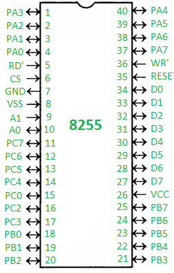
8255 Programmable
Peripheral Interface:
8255 is a programmable
peripheral IC which can be used to interface computer (CPU) to
various types of external peripherals
such as: ADC, DAC, Motor, LEDs, 7-segment displays, Keyboard, Switches etc. It has 3 ports
A, B and C and a Control word register. User can program the
operation of ports by writing
appropriate 8-bit .control word. into the control word register.

- PA0 – PA7 – Pins of port A
- PB0 – PB7 – Pins of port B
- PC0 – PC7 – Pins of port C
- D0 – D7 – Data pins for the transfer of data
- RESET – Reset input
- RD’ – Read input
- WR’ – Write input
- CS’ – Chip select
- A1 and A0 – Address pins
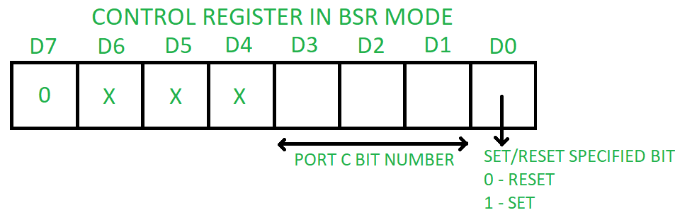
Operating modes –
- Bit set reset (BSR) mode –
If MSB of control word (D7) is 0, PPI works in BSR mode. In this mode only port C bits are used for set or reset.
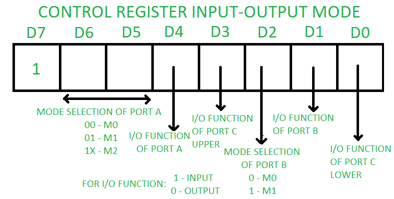
2. Input-Outpt mode –
If MSB of control word (D7) is 1, PPI works in input-output mode. This is further divided into three modes:
If MSB of control word (D7) is 1, PPI works in input-output mode. This is further divided into three modes:
- Mode 0 –In this mode all the three ports (port A, B, C) can work as simple input function or simple output function. In this mode there is no interrupt handling capacity.
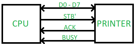
- Mode 1 – Handshake I/O mode or strobbed I/O mode. In this mode either port A or port B can work as simple input port or simple output port, and port C bits are used for handshake signals before actual data transmission. It has interrupt handling capacity and input and output are latched.Example: A CPU wants to transfer data to a printer. In this case since speed of processor is very fast as compared to relatively slow printer, so before actual data transfer it will send handshake signals to the printer for synchronization of the speed of the CPU and the peripherals.
- Mode 2 – Bi-directional data bus mode. In this mode only port A works, and port B can work either in mode 0 or mode 1. 6 bits port C are used as handshake signals. It also has interrupt handling capacity.
8.
a. Design and develop an assembly program to demonstrate BCD Up-Down
Counter (00-99) on the Logic Controller Interface.
8
– A - PROGRAM :
.model
small
.stack
20
.data
pa
equ 0e880h
pb
equ 0e881h
pc
equ 0e882h
ctrl
equ 0e883h
.code
mov
ax,@data
mov
ds,ax
mov
al,80h
mov
dx,ctrl
out
dx,al
mov
al,00h
aa:
add al,00h
daa
mov dx,pa
out dx,al
mov bx,5fffh
bb:
mov cx,8fffh
cc:
loop cc
dec bx
jnz bb
add al,01h
cmp al,9ah
jnz aa
mov
ah,4ch
int
21h
int
3
end
Output:
Counts from 00-99
8.
b. Design and develop an assembly program to read the status of two
8-bit inputs (X & Y) from the Logic Controller Interface and
display X*Y.
8
– B - PROGRAM :
.model
small
.stack
18
.data
pa
equ 0e880h
pb
equ 0e881h
pc
equ 0e882h
ctrl
equ 0e883h
.code
mov
ax,@data
mov
ds,ax
mov al,8ah
mov dx,ctrl
out dx,al
mov dx,pb
in
al,dx
mov bl,al
mov dx,pc
in
al,dx
mov cl,04h
ror al,cl
mul bl
mov dx,pa
out dx,al
mov
ah,4ch
int
21h
int
3
end
Output:
Take x=2(0010), Y=3(0011)
X*Y
should be 6 (0110)
9.Design and develop an assembly program to display messages “FIRE” and “HELP” alternately
with flickering effects on a 7-segment display interface for a suitable period of time. Ensure a
flashing rate that makes it easy to read both the messages (Examiner does not specify these delay
values nor is it necessary for the student to compute these values).

Port C – is used to select the next segment to display.
Character- a b c d e f g h
For eg F - 0 1 1 1 0 0 0 1 (71H)
P - 0 0 1 1 0 0 0 1 (31H)
.model small
.stack 64
.data
pa equ 0e880h
pb equ 0e881h
pc equ 0e882h
ctrl equ 0e883h
fire db 71h,9fh,11h,61h
help db 91h,61h,0e3h,31h
msg db 'press any key on kbd to return to dos','$'
.code
mov ax,@data
mov ds,ax
mov al,90h
mov dx,ctrl
out dx,al
mov ah,09h
lea dx,msg
int 21h
again:lea bp,fire
call disp
call delay
lea bp,help
call disp
call delay
mov ah,6h
mov dl,0ffh
int 21h
jz again
mov ah,4ch
int 21h
delay proc
mov ax,08fffh
agn1:mov cx,05fffh
agn:loop agn
dec ax
jnz agn1
ret
delay endp
disp proc
mov si,3
nxtchr:mov ah,8mov al,ds:[bp+si]
nxtseg:mov dx,pb
out dx,al
mov ch,al
mov al,0
mov dx,pc
out dx,al
mov al,0f0h
out dx,al
dec ah
jz below
mov al,ch
ror al,1
jmp nxtseg
below: dec si
cmp si,-1
jne nxtchr
ret
disp endp
end
Output: Display Fire and Help
.jpg)
9.Design and develop an assembly program to display messages “FIRE” and “HELP” alternately
with flickering effects on a 7-segment display interface for a suitable period of time. Ensure a
flashing rate that makes it easy to read both the messages (Examiner does not specify these delay
values nor is it necessary for the student to compute these values).
The above figure shows the seven segment arrangement
Port A – is used to send the data whole 8 bits at a timePort C – is used to select the next segment to display.
Common Anode
To display LED put 0 or else 1
For eg F - 0 1 1 1 0 0 0 1 (71H)
P - 0 0 1 1 0 0 0 1 (31H)
.model small
.stack 64
.data
pa equ 0e880h
pb equ 0e881h
pc equ 0e882h
ctrl equ 0e883h
fire db 71h,9fh,11h,61h
help db 91h,61h,0e3h,31h
msg db 'press any key on kbd to return to dos','$'
.code
mov ax,@data
mov ds,ax
mov al,90h
mov dx,ctrl
out dx,al
mov ah,09h
lea dx,msg
int 21h
again:lea bp,fire
call disp
call delay
lea bp,help
call disp
call delay
mov ah,6h
mov dl,0ffh
int 21h
jz again
mov ah,4ch
int 21h
delay proc
mov ax,08fffh
agn1:mov cx,05fffh
agn:loop agn
dec ax
jnz agn1
ret
delay endp
disp proc
mov si,3
nxtchr:mov ah,8mov al,ds:[bp+si]
nxtseg:mov dx,pb
out dx,al
mov ch,al
mov al,0
mov dx,pc
out dx,al
mov al,0f0h
out dx,al
dec ah
jz below
mov al,ch
ror al,1
jmp nxtseg
below: dec si
cmp si,-1
jne nxtchr
ret
disp endp
end
Output: Display Fire and Help
10.
Design and develop an assembly program to drive a Stepper Motor
interface and rotate the motor in specified direction (clockwise or
counter-clockwise) by N steps (Direction and N are specified by the
examiner). Introduce suitable delay between successive steps. (Any
arbitrary value for the delay may be assumed by the student).
.model
large
.stack
100
.data
n
equ 6
pa
equ 0e880h
pb
equ 0e881h
pc
equ 0e882h
ctrl
equ 0e883h
.code
mov
ax,@data
mov
ds,ax
mov
dx,ctrl
mov
al,80h
out
dx,al
mov
bh,n
up:mov
al,0eeh
call step
mov al,0ddh
call step
mov al,0bbh
call step
mov al,077h
call step
dec bh
jnz up
mov ah,4ch
int 21h
step proc near
push bx
mov dx,pc
out dx,al
mov bx,0ffffh
again:mov
cx,05fffh
agn:loop
agn
dec bx
jnz again
pop bx
ret
step endp
end
Outpt:
Stepper Motor rotates counter-clockwise direction.
11. a. Generate a Sine waveform using the DAC interface. (The output of the DAC is to be displayed on the CRO).;11a program to generate sine wave output ;give all supply voltages +5v,+12v,-12v and gnd. ;p1 connector red will go to gnd(Black) & orange will go to ;+ve (red) of CRO connector ;half wave generation .model small .stack 20 .data pa equ 010c0h pb equ 010c1h pc equ 010c2h ctrl equ 010c3h msg db 'press any key to return to DOS','$' tble db 100,117,134,150,164,177,187,194,198,204 db 198,194,187,177,164,150,134,117,100 db 90,80,70,60,50,40,30,20,10,0 db 0,10,20,30,40,50,60,70,80,90 .code mov ax,@data mov ds,ax mov dx,offset msg mov ah,09 int 21h mov al,80h mov dx,ctrl out dx,al mov bx,offset tble up:mov ah,06h mov dl,0ffh int 21h jnz quit mov dx,pa mov ch,4fh up1:mov cl,00 up2:mov al,cl xlat out dx,al inc cl cmp cl,33 jnz up2 dec ch jnz up1 jmp up quit:mov ah,4ch int 21h end
Output:
Sine wave on CRO


11.
b. Generate a Half Rectified Sine waveform using the DAC interface.
(The output of the DAC is to be displayed on the CRO).
;11 program to generate sine wave output
;give all supply voltages +5v,+12v,-12v and gnd.
;p1 connector red will go to gnd(Black) & orange will go to
;+ve (red) of CRO connector

;half wave generation
.model small
.stack 20
.data
pa equ 010c0h
pb equ 010c1h
pc equ 010c2h
ctrl equ 010c3h
msg db 'press any key to return to DOS','$'
tble db 100,117,134,150,164,177,187,194,198,204
      db 198,194,187,177,164,150,134,117,100
      db 100,100,100,100,100,100,100,100,100
      db 100,100,100,100,100
.code
mov ax,@data
mov ds,ax
mov dx,offset msg
mov ah,09
int 21h
mov al,80h
mov dx,ctrl
out dx,al
mov bx,offset tble
up:mov ah,06h
   mov dl,0ffh
   int 21h
   jnz quit
   mov dx,pa
   mov ch,4fh
up1:mov cl,00
up2:mov al,cl
    xlat
    out dx,al
    inc cl
    cmp cl,33
    jnz up2
    dec ch
    jnz up1
    jmp up
quit:mov ah,4ch
     int 21h
     end
Output: Half Sine wave on CRO

ARM Programming on Keil IDE Software

ARM Programming on Keil IDE Software
6.
To write and simulate ARM assembly language programs for data
transfer, arithmetic and logical operations (Demonstrate with the
help of a suitable program).
6
– A - PROGRAM :
area
prg1,code,readonly
entry
start
ldr
r1,=value
ldr
r2,[r1]
ldr
r4,=value
str
r3,[r4]
bx
lr
value
dcd
0x22222222
end
6
– B - PROGRAM :
area
pgm,code,readonly
entry
start
mov
r0,#0
mov
r1,#1
and
r2,r1,r0
orr
r3,r1,r0
eor
r4,r1,r0
bx
lr
end
6
– C - PROGRAM :
area
pgm3,code,readonly
entry
start
ldr
r0,=0x00000002
ldr
r1,=0x00000003
add
r2,r1,r0
muls
r3,r1,r0
bx
lr
end
Output:
Check Registers
7.
To write and simulate C Programs for ARM microprocessor using KEIL
(Demonstrate with the help of a suitable program)
7
– A - PROGRAM :
#include<LPC21xx.c>
int
main()
{
int
a=6,b=2,sum,mul,sub,div;
sum=a+b;
mul=a*b;
sub=a-b;
div=a/b;
}
7
– B - PROGRAM :
#include<LPC21xx.h>
int
main(void)
{
int
a=0,b=1,and1,or1,exor1,not1;
and1=a&b;
or1=a/b;
exor=a^b;
not1=~a;
}
Output:
Check command window
ARM Programming on LPC2148 with Keil IDE Software
ARM Programming on LPC2148 with Keil IDE Software
12.
To interface LCD with ARM processor-- ARM7TDMI/LPC2148. Write and
execute programs in C language for displaying text messages and
numbers on LCD
#include<lpc214x.h>
#include<stdio.h>
//Function
prototypes
void
lcd_init(void);
void
wr_cn(void);
void
clr_disp(void);
void
delay(unsigned int);
void
lcd_com(void);
void
wr_dn(void);
void
lcd_data(void);
unsigned
char temp1;
unsigned
long int temp,r=0;
unsigned
char *ptr,disp[] = " CSE DEPT ",disp1[] = "GNDECB";
int
main()
{
PINSEL0
= 0X00000000;
IO0DIR
= 0x000000FC;
lcd_init();
delay(3200);
clr_disp();
delay(3200);
temp1
= 0x81;
lcd_com();
ptr
= disp;
while(*ptr!='\0')
{
temp1 = *ptr;
lcd_data();
ptr ++;
}
temp1
= 0xC0;
lcd_com();
ptr = disp1;
while(*ptr!='\0')
{
temp1 = *ptr;
lcd_data();
ptr
++;
}
while(1);
}
void
lcd_init(void)
{
temp
= 0x30;
wr_cn();
delay(3200);
temp
= 0x30;
wr_cn();
delay(3200);
temp
= 0x30;
wr_cn();
delay(3200);
temp
= 0x20;
wr_cn();
delay(3200);
temp1
= 0x28;
lcd_com();
delay(3200);
temp1
= 0x0C;
lcd_com();
delay(800);
temp1
= 0x06;
lcd_com();
delay(800);
temp1
= 0x80;
lcd_com();
delay(800);
}
void
lcd_com(void)
{
temp
= temp1 & 0xf0;
wr_cn();
temp = temp1 & 0x0f;
temp = temp << 4;
wr_cn();
delay(500);
}
void
wr_cn(void)
{
IO0CLR
= 0x000000FC;
IO0SET
= temp;
IO0CLR
= 0x00000004;
IO0SET
= 0x00000008;
delay(10);
IO0CLR
= 0x00000008;
}
void
wr_dn(void)
{
IO0CLR
= 0x000000FC;
IO0SET
= temp;
IO0SET
= 0x00000004;
IO0SET
= 0x00000008;
delay(10);
IO0CLR
= 0x00000008;
}
void
lcd_data(void)
{
temp
= temp1 & 0xf0;
temp = temp ;//<< 6;
wr_dn();
temp= temp1 & 0x0f;
temp= temp << 4;
wr_dn();
delay(100);
}
void
clr_disp(void)
{
temp1 = 0x01;
lcd_com();
delay(500);
}
void
delay(unsigned int r1)
{
for(r=0;r<r1;r++);
}
Output:
Message in program
13.
To interface Stepper motor with ARM processor-- ARM7TDMI/LPC2148.
Write a program to rotate stepper motor
#include
<LPC21xx.h>
void
clock_wise(void) ;
void
anti_clock_wise(void) ;
unsigned
int var1 ;
unsigned
long int i=0,j=0,k=0;
int
main(void)
{
PINSEL2 = 0x00000000;
IO1DIR |= 0x00F00000;
while(1)
{
for(
j = 0 ; j < 50 ; j++ )
clock_wise() ;
for(
k = 0 ; k < 65000 ; k++ ) ;
for( j=0 ; j < 50 ; j++ )
anti_clock_wise()
;
for(
k = 0 ; k < 65000 ; k++ ) ;
}
}
void
clock_wise(void)
{
var1 = 0x00080000;
for(i=0;i<=3;i++)
{
var1
<<= 1 ;
IO1CLR
=0x00F00000;
IO1SET
= var1;
for(
k = 0 ; k < 3000 ; k++);
}
}
void
anti_clock_wise(void)
{
var1 = 0x00800000 ;
IO1CLR =0x00F00000 ;
IO1SET = var1 ;
for(k=0;k<3000;k++);
for(i=0;i<3;i++)
{
var1 >>=1;
IO1CLR =0x00F00000 ;
IO1SET=var1 ;
for(k=0;k<3000;k++);
}
}
Output:
Stepper motor rotates
No comments:
Post a Comment